S-T-L
-
regulaterz
- who u callin ne guy bruv

- Posts: 42
- Joined: Sat Apr 29, 2017 11:17 am
S-T-L
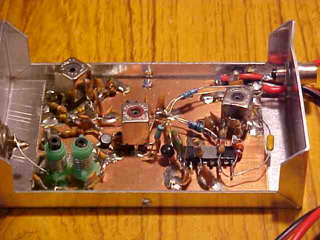
could you use something like this as a link to tx from studio? wit a bit of reverse engineering moding ect 
-
regulaterz
- who u callin ne guy bruv
- Posts: 42
- Joined: Sat Apr 29, 2017 11:17 am
Re: S-T-L
yes so you would use one PMR in studio and wire the other PMR up to the rig paired to each other on a private channel .thers a few good long range ones out ther with loads of channels they range from 400mhz to 460mhz .audio probly be a bit tin sounding i suppose as ther only ment for speech .not as they are strip it down and intergrate in to the rig
-
Albert H
- proppa neck!

- Posts: 3105
- Joined: Tue Apr 05, 2016 1:23 am
Re: S-T-L
PMR radios typically have an audio bandwidth from around 300Hz - 3kHz. This is about the same as an old wired telephone line. It's not sufficient bandwidth to get quality audio through (it's not even enough for medium wave!).
My most successful (and highest quality) links were WBFM in Band IV or V (the TV bands) tucked into the "guard bands" between TV channels. I used to use quite wide deviation - often 150kHz - and fairly low power at the transmitter. The aerials were always TV Yagis so the equipment was all built to match into 75Ω, and used low-loss TV coax for the feeders.
Most of the rig builders these days wouldn't be able to copy UHF stuff, so will tell you that it's too difficult or too expensive. Most of them are just numpties who copy other people's work (and it's always funny to see some idiot trying to get hold of some of the weird value parts that I used to throw in). Others just buy modules from established constructors and assemble them into boxes. Most have little or no idea exactly what they're doing.
I used to be able to throw together a little ½-Watt PLL tuned 600MHz transmitter for about £18 in parts. The receiver would cost a little less - about £15 in parts. The aerials and coax came from CPC (or anywhere else that sold cheap TV aerials) and cost about £30 for the pair. I used to sell these set-ups to pirates for about £285 for a transmitter and a receiver and aerials, and an extra receiver and aerial was £125.
If they wanted a stereo coder (or RDS later on), remote switching, audio processing or any other add-on, it'd cost more. It wasn't bad money for an evening's work back in those days!
"Why is my rig humming?"
"Because it doesn't know the words!"
"Because it doesn't know the words!"
-
regulaterz
- who u callin ne guy bruv
- Posts: 42
- Joined: Sat Apr 29, 2017 11:17 am
Re: S-T-L
-
Albert H
- proppa neck!
- Posts: 3105
- Joined: Tue Apr 05, 2016 1:23 am
Re: S-T-L
Happy New Year all. I'm sorting out the Band I RX layout at the moment. I only had a Gerber of the board that I used to use, so I need to convert it to something reasonable! I'm working on it now (as soon as I've finished the layout for something that's going to p[ay me money!)
"Why is my rig humming?"
"Because it doesn't know the words!"
"Because it doesn't know the words!"
-
Banus_radio
- no manz can test innit

- Posts: 124
- Joined: Wed Aug 24, 2016 9:58 pm
Re: S-T-L
http://213.114.131.21/_visitors/rx/linkrx.htm
Theres a vhf receiver circuit here which works well.
The bandpass filter looks wrong on the input though, Join the Hot side of the coils with something like a 1.8pf (between the coils)and cold sides of the coils to ground as shown in drawing.
Ill find the toko part numbers of coils L1 and T1 which are still available and easy to find on ebay. Ill update soon
You can also install a second 'L1' for double quad which will give slightly less distortion but the average ear will never notice the difference.
L3 and L4 wind 6 turns around 6mm diamater
The audio output from the CA3189 has a small component with a "?" in it, place an 10uf electroylitic cap here to decouple the audio path, + towards the ic, - will be audio out.
Also it would be good to add a varicap diode to the oscillator and add a simple pll, could use a tsa5511 and run the oscillator 10.7mhz higer than your band1 freq, tsa goes down to 60mhz, so you could receiver just under 50mhz using that ic.
Theres a picture here of a spidered wired band1 http://www.gareth.net.nz/nrgworkshop/ty ... ircuit.jpg
-
radium98
- proppa neck!
- Posts: 1006
- Joined: Fri Aug 26, 2016 7:01 pm
Re: S-T-L
use sprint layout this can convert it simplyAlbert H wrote: ↑Mon Jan 01, 2018 6:31 pm Happy New Year all. I'm sorting out the Band I RX layout at the moment. I only had a Gerber of the board that I used to use, so I need to convert it to something reasonable! I'm working on it now (as soon as I've finished the layout for something that's going to p[ay me money!)