I think their trying to get a single pole to resonate, would be much easier with a matching section going up the side, held away by a few cms, all you’d need would be a short lenght of wire to connect both elements to make it dc short, a choke at the bottom, have one in my loft at the moment, as the other aerial I had seemed over complecated. This seems a lot of length to go to for a single pole, you could also make an end fed dipole very easily, you could get to it right now, coax coming down over the bottom element, choke at the bottomFMEnjoyer wrote: ↑Fri Mar 21, 2025 10:37 am 1/2 wave end fed will be no better than a 1/4 ground plane antenna. It will have no gain over a dipole either as it is an end fed dipole.
You might need to choke the feed line otherwise any slight radiation pattern improvement over the 1/4 wave will be lost through feed line radiation. They are voltage fed so usually common mode on feed line should not be too bad.
The only possible advantage is mounting and no radials, it will also lose a little RF energy as heat in the matching coil meaning losses over a dipole.
Hope it works well for you.
Hi-Gain Vertical Half Wave Antenna
-
radionortheast

- proppa neck!

- Posts: 1233
- Joined: Wed Sep 09, 2015 1:38 pm
Re: Hi-Gain Vertical Half Wave Antenna
-
FMEnjoyer

- proppa neck!
- Posts: 611
- Joined: Sun Oct 12, 2014 1:33 pm
- Contact:
Re: Hi-Gain Vertical Half Wave Antenna
I made a J pole from wires and plastic pipes, sounds a bit like what you mention, it worked quite well, they seem fairly long, though I cannot compare it with anything else at that place for a random switch on thing, so accepted it for what it was. Matched fine, did what I wanted, I read they can also be much more susceptible to cmc on feed for some reason.
The dial is Glowing 88-108 , spin the wheel to light those Red LEDs , see signal needle rise.
-
Albert H
- proppa neck!
- Posts: 3130
- Joined: Tue Apr 05, 2016 1:23 am
Re: Hi-Gain Vertical Half Wave Antenna
Errr... No. The ½-wave vertical significantly out-performs both ¼-wave with groundplanes and the standard dipole - when correctly matched, and with a choke at the antenna end of the feeder, the radiation pattern is exactly the shape you want. It's truly omnidirectional, and the radiation pattern is best described as a flattened doughnut shape - there's more energy at useful elevations, with little or no upward radiation.
Practical experience shows that the field strength at distance from the antenna is consistently greater than that achieved with the dipole or ¼-wave with groundplanes.
"Why is my rig humming?"
"Because it doesn't know the words!"
"Because it doesn't know the words!"
-
FMEnjoyer
- proppa neck!
- Posts: 611
- Joined: Sun Oct 12, 2014 1:33 pm
- Contact:
Re: Hi-Gain Vertical Half Wave Antenna
It is fundamentally a 1/2 wavelength piece of wire, like a dipole and a 1/4 wave are a 1/2 wave pieces of wire. I always found the 1/4 wave a strange name for a dipole with multiple flared or horizontal radials. It is still physically 1/4 wave of + and 1/4 wave of -.
If we compare dipole with 1/2 wave end fed the sole difference is being fed at the end which means a lossy coil is needed. I am very curious as to the mechanism that produces this extra pattern flattening beyond a dipole ? Especially given the same current distribution over the antenna dimensions. At the very least even though they are best case maths models is to provide a computer model of this flattening.
It may be your 1/2 wave dipole and 1/4 were not installed well, site specifics, cmc on feeder. Mounting pole reflection/director in opposite direction to your field strength measurement site. The possible variables are endless when you start thinking about it.
When I cannot see a mechanism for pattern gain I personally consider it just wishful thinking.
The dial is Glowing 88-108 , spin the wheel to light those Red LEDs , see signal needle rise.
-
EFR

- tower block dreamin
- Posts: 263
- Joined: Mon May 20, 2024 5:39 pm
Re: Hi-Gain Vertical Half Wave Antenna
There is free tool, MMANA-GAL for Windows to desing antennas and see the radiation pattern from your desing.FMEnjoyer wrote: ↑Sat Mar 22, 2025 10:56 am It is fundamentally a 1/2 wavelength piece of wire, like a dipole and a 1/4 wave are a 1/2 wave pieces of wire. I always found the 1/4 wave a strange name for a dipole with multiple flared or horizontal radials. It is still physically 1/4 wave of + and 1/4 wave of -.
If we compare dipole with 1/2 wave end fed the sole difference is being fed at the end which means a lossy coil is needed. I am very curious as to the mechanism that produces this extra pattern flattening beyond a dipole ? Especially given the same current distribution over the antenna dimensions. At the very least even though they are best case maths models is to provide a computer model of this flattening.
It may be your 1/2 wave dipole and 1/4 were not installed well, site specifics, cmc on feeder.
When I cannot see a mechanism for pattern gain I personally consider it just wishful thinking.
Its quite easy to use.
Fight For Free Radio!
-
shuffy
- tower block dreamin
- Posts: 486
- Joined: Sun Oct 05, 2014 3:55 pm
Re: Hi-Gain Vertical Half Wave Antenna
Definitely. I think I've banged on about this elsewhere on here but EZNEC / 4NEC2 are also really useful, literally lost count of the number of antennas I've built over the years with the help of these tools and the simulations are always gobsmackingly accurate. Haven't used MMANA-GAL - does it use the same NEC simulation engine under the hood?
In terms of the NRG vertical - it would seem to be all about the radiation pattern, that's why I've been trying to get one working all this time.
He said shuffy! I said WOT? Woo!
-
EFR
- tower block dreamin
- Posts: 263
- Joined: Mon May 20, 2024 5:39 pm
Re: Hi-Gain Vertical Half Wave Antenna
I think it had its own engine, EZNEC is always been hard to learn for me, MMANA-GAL is just fine for my stuff.shuffy wrote: ↑Sat Mar 22, 2025 12:52 pmDefinitely. I think I've banged on about this elsewhere on here but EZNEC / 4NEC2 are also really useful, literally lost count of the number of antennas I've built over the years with the help of these tools and the simulations are always gobsmackingly accurate. Haven't used MMANA-GAL - does it use the same NEC simulation engine under the hood?
In terms of the NRG vertical - it would seem to be all about the radiation pattern, that's why I've been trying to get one working all this time.
I was able to get ground conductive data from local geology institute, so measurements are about right.
Fight For Free Radio!
-
FMEnjoyer
- proppa neck!
- Posts: 611
- Joined: Sun Oct 12, 2014 1:33 pm
- Contact:
Re: Hi-Gain Vertical Half Wave Antenna
I did a quick model of a end fed and a dipole at 80m pretending on a 20 storey block and the gain difference is within 0.3db in favour of dipole
patterns look the same will upload at some point. 1.5m of wire is 1.5m of wire. A model is rubbish really because we cannot model a tower block with all the iron inside the structure I did it over normal ground. The only tiny advantage is that a 1/2 wave end fed would have the current centre 1/4 wave length higher than dipole through mount method alone.
I bet any differences are purely to do with mounting pole interactions. If you put a 1/4 wave up and put all 4 radials on one side it becomes a bit directional that may even be an advantage in some situations.
The dial is Glowing 88-108 , spin the wheel to light those Red LEDs , see signal needle rise.
-
radionortheast
- proppa neck!
- Posts: 1233
- Joined: Wed Sep 09, 2015 1:38 pm
Re: Hi-Gain Vertical Half Wave Antenna
It does look more like a j, much shorter, don’t use a transmitter that much, it can work at any frequency, with low power useful for a rainy day. I’ve managed to get very short poles to match at a low frequency, the matching wire can’t go up along the main pole when the main pole is short, it has to be more like a loop at the bottom of it, or going up a short distance. I do think having a pole does produce or more nice round pattern I might be imagining it, a short pole can be very light go high up, I could still pick up 0.5w 4 miles away. The other I had was at right wavelenght, did have a stereo signal coming through on low power, it did seem to work better than anything else, or maybe just the frequency, you don't have the boom arm, radials coming out at the bottom, it makes everyone happy.FMEnjoyer wrote: ↑Fri Mar 21, 2025 8:19 pm I made a J pole from wires and plastic pipes, sounds a bit like what you mention, it worked quite well, they seem fairly long, though I cannot compare it with anything else at that place for a random switch on thing, so accepted it for what it was. Matched fine, did what I wanted, I read they can also be much more susceptible to cmc on feed for some reason.
rabbit ears,
-
FMEnjoyer
- proppa neck!
- Posts: 611
- Joined: Sun Oct 12, 2014 1:33 pm
- Contact:
Re: Hi-Gain Vertical Half Wave Antenna
For a GPA it becomes slightly directional in the direction the radials point. I suspect it would possibly change the angle of radiation for the other side though. I just thought I would mention it in passing.
There are these
dipole
https://ibb.co/5hMtccKV
1/2 wave fed at end
https://ibb.co/20cbSfky
Quarter wave ground plane 4 radials
https://ibb.co/hxcB4LcG
According to these plots they are the same with fractions of db. Of course the very big variable of a tower block structure under the antenna could have unknown effects on the RF making one antenna design more or less favourable than another for the real world scenario of a load of concrete and iron girders underneath. The interaction with that may possibly change from antenna to antenna meaning one appears to perform better, no idea and rather unmeasurable. Unless the field strength readings were done with with great stringency to method.
plots are what they are 'some basic comparison between predetermined, non real world ideals'
The dial is Glowing 88-108 , spin the wheel to light those Red LEDs , see signal needle rise.
-
Albert H
- proppa neck!
- Posts: 3130
- Joined: Tue Apr 05, 2016 1:23 am
Re: Hi-Gain Vertical Half Wave Antenna
In my youth, I spent a lot of time on an "Antenna Range". This was a barn of a place, with a transmitter that ran at about 1 GHz, allowing the test aerials and receiving aerials to be small, and allow tests over many wavelengths distance. During the course of my experimentation, I tried many aerial configurations, and many matching schemes.
I found that the best simple vertical aerial was (probably) the ⅞-wave with groundplane. The flattened radiation pattern got the signal out in the direction I wanted it to go. I also tried the ½-wave vertical, but due to its extremely high feedpoint impedance, I couldn't get a good match.
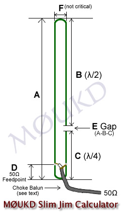
One of the guys I was working with pointed out that a J-pole is effectively a ½-wave radiator, with a ¼-wave matching stub at the bottom. Even the J-pole is tricky to match, but not impossible. It behaves much like the "ideal" ½-wave once you get it to match, but is ¾-wave long....
Ultimately, there's no ideal aerial, and something that works well in one site is useless in another.
What I really discovered in all my experimenting is that matching is crucial, and the more metal you put in the air, the more you radiate!
I found that the best simple vertical aerial was (probably) the ⅞-wave with groundplane. The flattened radiation pattern got the signal out in the direction I wanted it to go. I also tried the ½-wave vertical, but due to its extremely high feedpoint impedance, I couldn't get a good match.
One of the guys I was working with pointed out that a J-pole is effectively a ½-wave radiator, with a ¼-wave matching stub at the bottom. Even the J-pole is tricky to match, but not impossible. It behaves much like the "ideal" ½-wave once you get it to match, but is ¾-wave long....
Ultimately, there's no ideal aerial, and something that works well in one site is useless in another.
What I really discovered in all my experimenting is that matching is crucial, and the more metal you put in the air, the more you radiate!
"Why is my rig humming?"
"Because it doesn't know the words!"
"Because it doesn't know the words!"
-
FMEnjoyer
- proppa neck!
- Posts: 611
- Joined: Sun Oct 12, 2014 1:33 pm
- Contact:
Re: Hi-Gain Vertical Half Wave Antenna
I can only wonder why almost no one speaks of the 7/8 wave myself. It models very poorly as well. So either modelling is broken or something else is amiss. Most energy goes upwards according to a model under same conditions as opposed to the horizon. It has neg 11dB gain compared to all other 3 above.
https://ibb.co/4Z79zrJn
Antenna performance is wavelength vs ground dependent. The multiples or fractions of wavelength above the ground the antenna is mounted has a massive influence on the pattern so 1gHz testing is good for 1gHz antennas at whatever precise height above ground it was in testing.
The ground is part of the antenna system as it is part of the overall circuit. Models whilst imperfect, at least level the playing field and show comparative patterns for given input data.
If it works it works, personally given what I see I would stick with a GPA myself as the match is lossless. Coil matching is a little lossy and I guess the pawsey stub on a dipole is ever so slightly lossy.
The dial is Glowing 88-108 , spin the wheel to light those Red LEDs , see signal needle rise.
-
FMEnjoyer
- proppa neck!
- Posts: 611
- Joined: Sun Oct 12, 2014 1:33 pm
- Contact:
Re: Hi-Gain Vertical Half Wave Antenna
I think I made the Slim Jim variant not the J pole, they are very similar. Thin tube to hold wire, thick tube for weatherproofing. I love the 1/4 wave, easy, effective, lossless match.
The dial is Glowing 88-108 , spin the wheel to light those Red LEDs , see signal needle rise.
-
EFR
- tower block dreamin
- Posts: 263
- Joined: Mon May 20, 2024 5:39 pm
Re: Hi-Gain Vertical Half Wave Antenna
There is something wrong on your modeling, or I think so.
Try just simple dipole and fullwave loop at same settings and get screenshots?
Edit: You had dipole already, something wrong on settings, I take look at morning.
Try just simple dipole and fullwave loop at same settings and get screenshots?
Edit: You had dipole already, something wrong on settings, I take look at morning.
Fight For Free Radio!
-
FMEnjoyer
- proppa neck!
- Posts: 611
- Joined: Sun Oct 12, 2014 1:33 pm
- Contact:
Re: Hi-Gain Vertical Half Wave Antenna
Had a look, element length, vertical, radials or not, frequency, ground type, elevation 80m asl same setting for each. I think it well known 5/8 is as long as people go and even that is questionable at best. I will relax and let someone disprove it, no great shakes if ithey do.
"The gain - at frequency - is around 2.8 dBd "
If it is a reality that would be really something, everyone can use 1/2 the power and reduce the cost of their rig acquisition.
"The gain - at frequency - is around 2.8 dBd "
If it is a reality that would be really something, everyone can use 1/2 the power and reduce the cost of their rig acquisition.
The dial is Glowing 88-108 , spin the wheel to light those Red LEDs , see signal needle rise.
-
shuffy
- tower block dreamin
- Posts: 486
- Joined: Sun Oct 05, 2014 3:55 pm
Re: Hi-Gain Vertical Half Wave Antenna
So I did a test with my NRG effort using very low power from a high location. Not scientific at all but observations seemed to confirm the theory of less "downward" radiation. I might have another go soon using a more realistic power level but won't be until after Easter 
He said shuffy! I said WOT? Woo!
-
Albert H
- proppa neck!
- Posts: 3130
- Joined: Tue Apr 05, 2016 1:23 am
Re: Hi-Gain Vertical Half Wave Antenna
It's really useful to minimise downward radiation. If the rig's up a block, you prevent lots of signal annoying the people below, and it can make the field strength very low at the foot of the block - this has worked in my favour many times - people trying to locate the gear often don't realise that it's above them! This has saved gear from both the DTI and rig thieves!
"Why is my rig humming?"
"Because it doesn't know the words!"
"Because it doesn't know the words!"
-
Gigahertz
- tower block dreamin
- Posts: 275
- Joined: Fri May 08, 2015 6:42 pm
Re: Hi-Gain Vertical Half Wave Antenna
A year after my first attempt, I finally had time to try the top end of the band.
You do not have the required permissions to view the files attached to this post.
-
shuffy
- tower block dreamin
- Posts: 486
- Joined: Sun Oct 05, 2014 3:55 pm
Re: Hi-Gain Vertical Half Wave Antenna
Fantastic job Gigahertz. What's your white pipe made from (the part with the coils wound round)?
Mine works well but I've yet to try it on high power, I might shove a couple of hundred Watts up it and see how we go.
Mine works well but I've yet to try it on high power, I might shove a couple of hundred Watts up it and see how we go.
He said shuffy! I said WOT? Woo!
-
Gigahertz
- tower block dreamin
- Posts: 275
- Joined: Fri May 08, 2015 6:42 pm
Re: Hi-Gain Vertical Half Wave Antenna
Cheers Shuffy,
The pipe is just 20mm approx from B&Q or Wickes.
I found that due to the diameter of the pipe, I used fewer turns on the top coil. I started with 4 turns and just took off a quarter each time I did a test. The bottom coil is 3 and a half turns.
As Lee mentioned, using a Teflon pipe, the 50W version should handle 150 watts