Page 2 of 3
Re: 8W + PLL + Stereo + RDS
Posted: Wed Jun 05, 2024 2:10 pm
by radionortheast
Albert H wrote: ↑Tue Jun 04, 2024 11:25 pm
However, I can imagine that some people trying to select their frequency will find it difficult!
I guess you have to turn the trimmer?

i'm not sure what else you would do! this is something i'm quite interested in, think its still quite hard when it comes to programming, another thing I think to go wrong, making an oscillator is hard, a pll even harder, the prescaler pll transmitter doesn't need programming, then you have the dip switches and the trimmer, code for the dip switches, selecting frequency is hard.
Re: 8W + PLL + Stereo + RDS
Posted: Wed Jun 05, 2024 2:55 pm
by 1608cc
To change frequency you have to edit eeprom data of attiny13 (as on the photo on prev page). This micro has only 6 GPIO we can use, and there wasn't space for dipswitches. For me it isn't a problem because I work with electronics everyday.
The trimmer doesn't change freq itself - its main purpose is to change tune voltage of PLL to be set ~2.5-3V to get ideal characteristics of varicaps that pass MPX/Audio in best quality. When you increase capacitance using trimmer then PLL rise voltage to drop capacitance of varicaps - resulting capacitance stays same, so frequency is also same as before tunning trimmer. When you drop on trimmer value, then situation of PLL behaviour is opposite.
Re: 8W + PLL + Stereo + RDS
Posted: Thu Jun 06, 2024 8:48 am
by radionortheast
That makes sense, with the transmitter I used to have used the sab6456, use the trimmer to get a lock, its also best to get the correct voltage, to do with sound to get the best?, does using different varicaps make a difference in the sound, I suppose its not that hard to get the right ones just wondering.
When it comes to making things I can make kits, putting something like a pll together is quite daunting, i'm considering having a go, making it on breadboard..
Re: 8W + PLL + Stereo + RDS
Posted: Thu Jun 06, 2024 10:17 am
by Krakatoa
1608cc wrote: ↑Wed Jun 05, 2024 2:55 pm
To change frequency you have to edit eeprom data of attiny13 (as on the photo on prev page). This micro has only 6 GPIO we can use, and there wasn't space for dipswitches. For me it isn't a problem because I work with electronics everyday.
I guess another way to program the frequency would be to implement a serial command prompt: plug in an usb to serial ttl converter to the Attiny, this would send a line with the commands available and then the user would enter the new frequency, then a command to save to eeprom and that's it. I think this attiny13 would have the capability to do that with is 1k(?) program memory.
Re: 8W + PLL + Stereo + RDS
Posted: Thu Jun 06, 2024 12:41 pm
by 1608cc
radionortheast wrote: ↑Thu Jun 06, 2024 8:48 am
does using different varicaps make a difference in the sound, I suppose its not that hard to get the right ones just wondering.
Exacly - the important parameter is a capacitance delta VS voltage delta. Can say it is varicap capacitance slope. Good examples are BBxx9 diodes - BB109, BB209, BB329, BB529, BB809, BBY40 etc. - a small change of voltage gives large change in its capacitance. Diodes such as BB105 or BB204 are worse than "9-end" varicaps in this case.
For example - basing on Veronica VCO - putting BB204 in circuit causes in lower volume in receiver, without changing anything else

The mpx signal amplitude is same, but the same voltage swing produces less change in varicap capacitance. Less capacitance variance = less frequency variance, and as we using FM modulation - lower volume, due to shallow modulation. Using BB109, makes FM modulation deeper, so volume is higher - with same input amplitude. Ofc we can increase mpx level for BB204, but we can get out from linear part of characteristic, or when voltage starts to be higher on anode, varicap will start conducting like a regular diode, and produce huge amount of distortions.
So when somebody says that varicap type doesn't matter, "you can use even LED", "it works with any varicap" - don't listen to them

Krakatoa wrote: ↑Thu Jun 06, 2024 10:17 am
I guess another way to program the frequency would be to implement a serial command prompt: plug in an usb to serial ttl converter to the Attiny, this would send a line with the commands available and then the user would enter the new frequency, then a command to save to eeprom and that's it. I think this attiny13 would have the capability to do that with is 1k(?) program memory.
Can be do that way. Even can put Attiny85 with 8kb flash in place of attiny13, so code space won't be a problem.
Re: 8W + PLL + Stereo + RDS
Posted: Fri Jun 07, 2024 9:55 pm
by Albert H
The deviation sensitivity / varicap voltage swing can be crucial, but isn't only dependent on the varicap type - the circuit configuration is important too. I always design VCOs so that the modulation sensitivity is such that you need at least 500 mV p-p for full 75 kHz deviation. One well-known.commercial design I saw needed just 5.5 mV p-p for 75 kHz deviation, and it was impossible to prevent it from humming!
The amusing thing is that LEDs make very good varicap diodes (with remarkably good linearity), and don't go into forward conduction until about 2 V or so (the Vf varies with colour and type of LED). Experience shows that green LEDs seem to exhibit the biggest capacitance when reverse-biased, making them the best choice for use as varicaps. If you're going to do that, be certain to shield the LEDs from mains-powered lighting, as otherwise their inherent photo-electric sensitivity will cause hum on the modulation! There are several well-respected commercial VHF FM exciters that use LEDs as varicaps, so I don't understand your antipathy towards them.
Incidentally, the first commercial FM exciters I ever worked on used "reactance modulation". Other designs used "phase modulation" which resolves as FM, but is difficult to linearise - they needed a "pre-distortion" circuit to overcome the limitations of the modulation system! Those were valved designs, with some very high voltages around, and semiconductor variable capacitance diodes wouldn't work very well in that environment.
Re: 8W + PLL + Stereo + RDS
Posted: Fri Jul 05, 2024 1:43 am
by 1608cc
Today, assembled everything in enclosure

obraz_2024-07-05_023823276.png
3D printed front panel...
obraz_2024-07-05_023902750.png
Also did some tests with new J-pole (SWR 1.04). Max range in straight line is 13,7km @ 9W (13.8V supply, and gently tune

)
obraz_2024-07-05_023957815.png
obraz_2024-07-05_024019616.png
Re: 8W + PLL + Stereo + RDS
Posted: Fri Jul 05, 2024 3:01 am
by Albert H
radionortheast wrote: ↑Thu Jun 06, 2024 8:48 am
does using different varicaps make a difference in the sound, I suppose its not that hard to get the right ones just wondering.
When it comes to making things I can make kits, putting something like a pll together is quite daunting, i'm considering having a go, making it on breadboard..
The varicap type has little effect on the sound, as long as you're using it in the linear part of its characteristic. Different varicaps have differing lowest (and highest) capacity values, and different sensitivities (how much the capacitance changes pervolt of reverse bias). ANY diode can act as a varicap (to a greater or lesser extent) if it's reverse-biased at a voltage lower than its breakdown (or "zener") voltage. I've even used LEDs as varicaps in some circuits.
PLL's are actually quite simple, but you're unlikely to be able to construct one for VHF on "breadboard". You have to bear in mind that layout is crucial at higher frequencies. Lead lengths have to be kept short, and you do all you can to minimise the length of the RF path through your circuits.
Re: 8W + PLL + Stereo + RDS
Posted: Fri Jul 05, 2024 3:07 am
by Albert H
1608cc: That looks like a tidy job! You might want to paint your J-pole to stop it corroding. I used to use acrylic paint - usually pale grey, so the aerial was virtually invisible from ground level!
Re: 8W + PLL + Stereo + RDS
Posted: Fri Jul 05, 2024 3:38 pm
by radium98
Is j-pole better in coverage for small area then a dipole ? where site of view is visible and the radius is about 7 Km
Re: 8W + PLL + Stereo + RDS
Posted: Fri Jul 05, 2024 3:56 pm
by 1608cc
Albert H wrote: ↑Fri Jul 05, 2024 3:07 am
1608cc: That looks like a tidy job! You might want to paint your J-pole to stop it corroding. I used to use acrylic paint - usually pale grey, so the aerial was virtually invisible from ground level!
Maybe someday, when I gonna feel artistic
. I use it just for test not for a regular broadcasting so it can shining anyway.
radium98 wrote: ↑Fri Jul 05, 2024 3:38 pm
Is j-pole better in coverage for small area then a dipole ? where site of view is visible and the radius is about 7 Km
On paper have the same dBi parameters. In real, couldn't say... I used to have half-wave dipole but only with few mW - coverage 100-200m only. The main reason I switched to j-pole is mounting position - it is straight and doesn't need much space around, so just screewed it to chimney without any boom.
Re: 8W + PLL + Stereo + RDS
Posted: Fri Jul 05, 2024 7:57 pm
by EFR
Very nice looking box.
Re: 8W + PLL + Stereo + RDS
Posted: Fri Jul 05, 2024 9:02 pm
by radium98
informative . thanks
Re: 8W + PLL + Stereo + RDS
Posted: Fri Jul 05, 2024 10:35 pm
by 1608cc
If someone is interested, I used NanoVNA to tune the antenna. Quite accurate and cheap tool.
obraz_2024-07-05_233234819.png
obraz_2024-07-05_233255329.png
Also designed a 50ohm dummy (with voltage probe up to 100V - 100W) using 2W resistors - cause before I used only two 100 ohm in parallel and need to put them into oil bath to dissipation 10W :p
obraz_2024-07-05_233454265.png
Re: 8W + PLL + Stereo + RDS
Posted: Fri Jul 05, 2024 11:44 pm
by rigmo
1608cc wrote: ↑Fri Jul 05, 2024 10:35 pm
obraz_2024-07-05_233454265.png
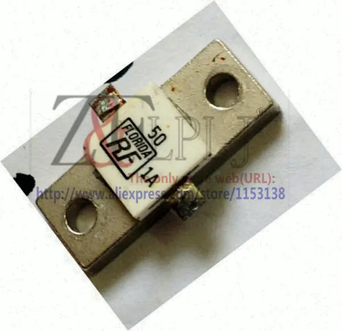
good work but no good results...
Nothing can replace single resistance...
https://zflplj.com/en/products/
only 2usd
Re: 8W + PLL + Stereo + RDS
Posted: Sat Jul 06, 2024 12:14 am
by 1608cc
I agree. But it is still better than nothing.
Re: 8W + PLL + Stereo + RDS
Posted: Sat Jul 06, 2024 2:03 pm
by Albert H
1608cc wrote: ↑Fri Jul 05, 2024 3:56 pm
On paper have the same dBi parameters. In real, couldn't say... I used to have half-wave dipole but only with few mW - coverage 100-200m only. The main reason I switched to j-pole is mounting position - it is straight and doesn't need much space around, so just screewed it to chimney without any boom.
The J-pole is more difficult to tune accurately, but the results are excellent when you get it right. It's interesting to compare the radiation shapes of the J-pole against the dipole. If the dipole is correctly fed (through a Pawsey Stub to make the output balanced), the results can be good, but in practice, you find that the upper arm of the dipole is responsible for most of the radiation, with the lower arm really just providing a counterpoise. Effectively, the dipole is radiating like a ¼-wave vertical that's matched.
The J-pole is working more like a ½-wave vertical, with a matching section below it. Theoretically, a ½-wave vertical has an infinite impedance at its feedpoint, so some kind of matching has to be done to bring down the feedpoint impedance to 50Ω. The lower third of the aerial is that matching section. The reason that the J-pole seems to give a better signal at distance is because the radiation pattern - if it's correctly matched - is like a flat doughnut, with little energy going upwards or downwards. You also have the advantage that the radiating part is a full ½-wave long.
Practical experience shows that more metal in the air usually means a better signal!
The convenience of the vertical J-pole also wins over a dipole - it's
much easier to mount, and doesn't suffer from needing a boom (the number of dipoles I've seen on bent poles is huge!).
The old NRG Halfwave vertical worked well too. The extremely high feedpoint impedance of the radiator is transformed by the coils and capacitor matching section under the cowl. The problem with the aerial is that the capacitor would flashover in damp air when trying to run higher power throught the thing!
My favourite aerial is the slotted colinear. I've built them with as much as 10dB of real gain (100 Watts in gives an ERP of 1 kW!). It's a hell of a lot of metal in the air, and they're huge, but it's often the cheapest power amplification method!
Re: 8W + PLL + Stereo + RDS
Posted: Sun Jul 07, 2024 6:52 am
by radium98
valuable passianate thanks
Re: 8W + PLL + Stereo + RDS
Posted: Sun Jul 14, 2024 10:02 am
by Hugh
Your audio input circuit shows a block MPX filter, what have you used there? A Toyo block, or a wee circuit?
Great build.
Re: 8W + PLL + Stereo + RDS
Posted: Sun Jul 14, 2024 9:41 pm
by 1608cc
It is "FDP-02" filter from old polish Unitra Diora tuner (AS-252). Basically it's Toko 19kHz LPF equivalent.
26dB @ 19kHz and 50dB @ 38kHz.
obraz_2024-07-14_224047723.png
obraz_2024-07-14_224129588.png